If you want to make reamers for cutting flute bores it’s going to be a saga. At least for me. In this my first thread here I’m going to post photos documenting my experience, starting with how I made a taper jig and later with resulting tapered rods, milled but warped one-slot reamers, and finally (I hope) with straight multi-slot reamers.
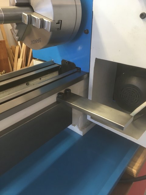
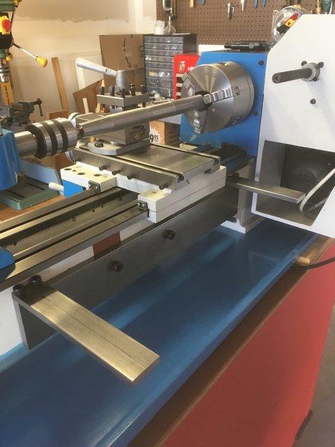
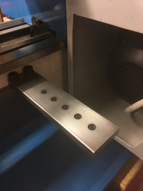
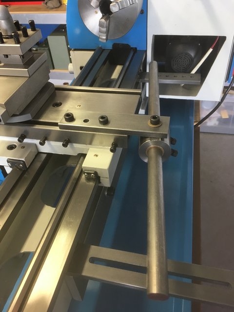
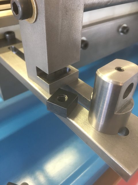
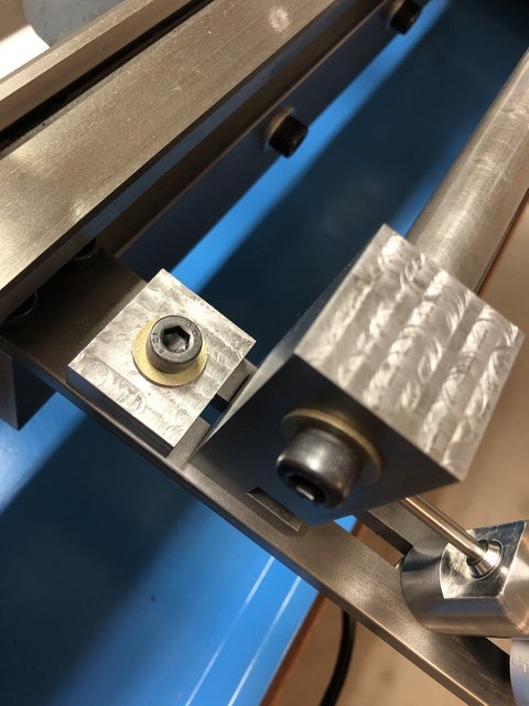
So let’s begin. First, I bought some steel plate, cleaned it up, drilled and tapped a few holes, and attached the foundation to a small Chinese lathe.
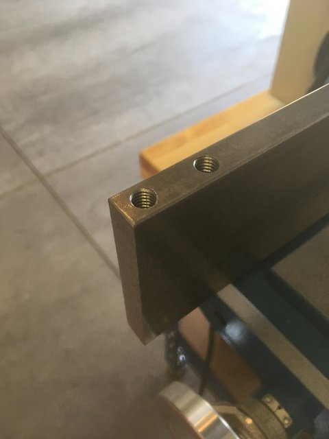
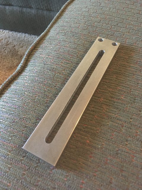
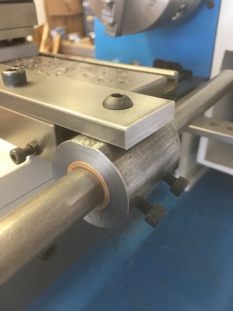
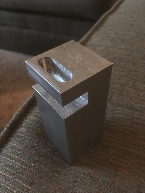
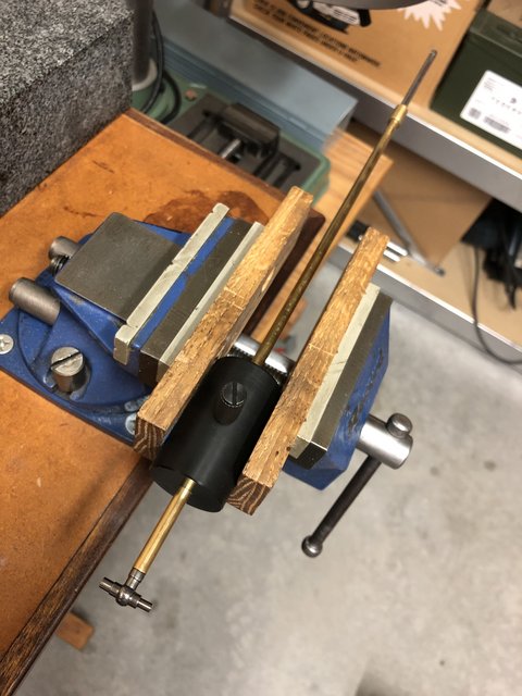
Then it was time to make some little posts to connect things, one with a slot to make up for the fact that I didn’t have the means to mill a slot with a radius in the support. (The post is upside down here.)
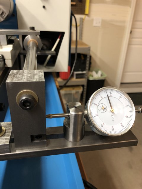
A dial indicator to keep track of the degree of taper. Distance from point of pivot to point of movement is 18.75" but it can easily be converted to taper-per-foot with 8th grade math.
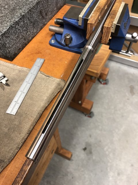
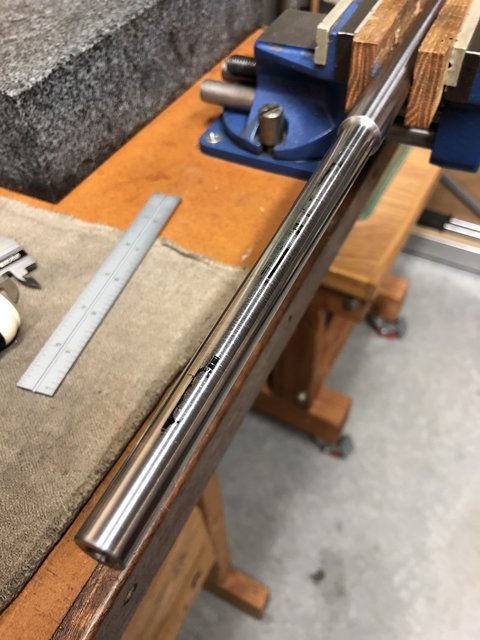
I was worried that my taper attachment would be too weak and flex too much, so I made many light passes and everything turned out fine. The taper was inside .001" of my intentions.
WARNING!! If you try this yourself please design a safety protocol to prevent yourself from ever bolting on your taper jig before disengaging your cross slide screw. Engaging both at once will crash your lathe. Treat this like you treat firearms safety rules or helicopter pre-flight check lists. Double check. Triple check. Every time!
William, this is hugely impressive–you clearly have advanced machining skills and excellent problem-solving techniques! I think your solution is elegant, though it does seem to be confined to making straight tapers, is that correct?
The only thing that struck me as a potential down-side (and I really had to stop drooling over the lovely machining you did to even evaluate any possible limits) is if you wish to create a taper that has perturbations in it.
When I made my first “Irish” flute (and this might be repetitive if you’ve read through the older threads on reamer making) I tried to make my life easier by doing a straight taper, which was a clear departure from the data I had gotten from Terry that came from his original Pratten flute. The straight taper made a really nice flute, but my flutes did not attain that next plateau until I returned to the original data, which indicated a bore with a fair number of “bumps” and “dips” along it’s length. Past flute makers definitely used a “wiggly” bore to enhance tuning/harmonics, and even though many of the perturbations are quite small, the cumulative effect is profound.
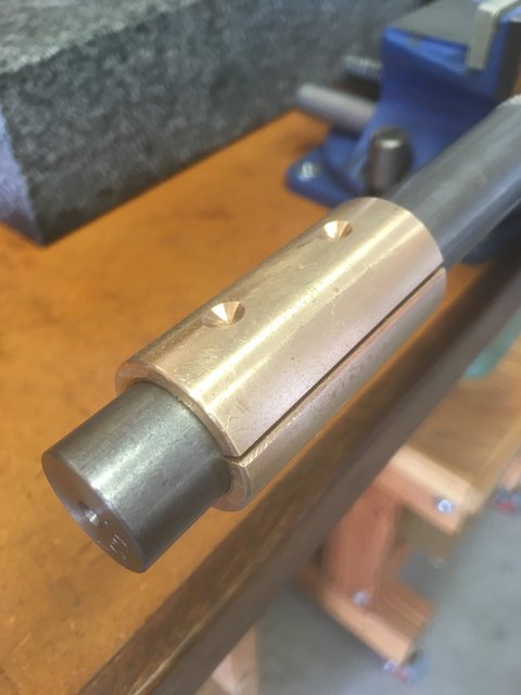
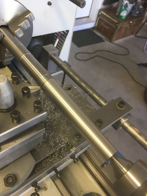
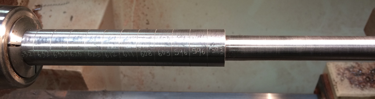
The only way in which I was able to create a taper with the proper pertubations was to turn it incrementally. I took my steel stock and marked my data points along it’s length (I made very shallow grooves at 10mm intervals for visibility) and then I marked (with an engraver) the target diameter of each data point. Then I hung a few inches of it outside the headstock spindle (I’m using a collet chuck) and supported it with the tailstock as well. I work each individual data point down until it is at the target diameter (actually .003" over the target because I sand it smooth afterwards). Once my data point is correct, I move along and do the next one. Once I’m up against the headstock/collet, I pull out a few inches more of stock and start again. This means that the stock that I’m working is never more than 4" away from the spindle head, so there is no chatter or flex. You can see a photo below of what the in-progress taper looks like.
This method is slow and requires me to take a LOT of measurements with my micrometer along the way, doing delicate finish cuts to maintain accuracy. I can actually blend the steps as I go with some “freehand” control of the tool (riding the x and y axis controls) and then finish with sandpaper. This method consistently gets me within about .001" of my target, which is plenty accurate for a reamer.
Thanks so much for your thoughtful and very kind reply. I’ve got a million questions and maybe a few observations, but alas! other duties to attend to before I can jot them down.
Thanks for your compliments about my machining skills. Low res pictures make my work look very impressive!
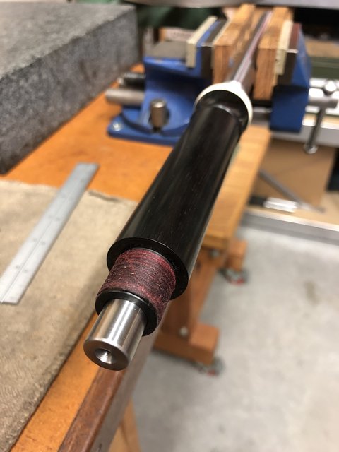
Yes, my solution works best with straight tapers, but with a little manipulation I can make certain alterations. Carefully charting order of operations; plotting when and where to stop a cut, change a rate of taper, or switch to cylindrical turning allows for something other than a straight taper. One of my reamer profiles, the left-hand joint of a four-piece baroque flute, starts with a cylindrical section at the big end, changes to a shallow taper for a good bit of its length, and then transitions to a steeper taper toward the small end.
I have to admit I don’t understand how you get “perturbations” in a ream if you are using a tapered reamer. Surely everything “behind” the widest point in the taper is going to be as wide as the widest part of the taper?
Thanks for nudging me to drag out all my old files on bore profiles as they relate to intonation and response (even some from the 80s and one from a college course I took on musical acoustics in the 70s!) and go over my thinking once again and from the beginning.
I had thought that small “perturbations” in bore profiles were unintentional. When I first got interested in making a flute, I obtained drawings and other measured data sets related to one particular 18th century flute maker. What I noticed when I laid graphs on top of each other was an “average” that I took for an original intention–or even a peek at the shape of an original reamer–and “perturbations” that looked like a combination of wood change over time, inaccuracies in measurement (I have two drawings of the SAME flute based on measurements taken by different individuals at different times that contradict considerably!), and, speculatively, bore alterations made by someone later. I even took the trouble to measure a couple of bores myself at different temperatures and humidity levels and got different graphs from the same flute using the same measuring tools set up on the same bench!
When measuring modern reproductions, I’ve noticed something very close to the average I saw when superimposing graphs.
Years ago there was a minor fad among trumpet players that involved having factory leader pipes (the first section of tubing after the mouthpiece) replaced with custom leader pipes with stepped bores. The guy making the stepped bores had good marketing copy and lots of fancy brochures with intonation charts and testimonials from a few good players, but it all died down after a while and everybody just went back to their more traditional leader pipes that were basically a straight taper or variations on a parabola. That episode stuck in my mind and influenced me when I saw small variations in flute drawings.
I’m new to this forum. Would you be so kind as to provide links to other discussions here about reamer making?
This thread: https://forums.chiffandfipple.com/t/rockstro/101821/1 is very much to the point. It’s long, it’s loaded with info, it’s intense at times, but it deals extensively with this very topic and I think you’ll find it worth reading (all ten or so pages of it!).
When I use the word “perturbation” (and it’s possible that I’m not using it correctly!) I’m talking about variations from a straight line in the taper, but with those variations always being in a continually descending diameter. Not “chambering”, obviously (as discussed in the famous Rockstro thread I just linked to). But instead of that straight line that makes a perfect “cone” out of the bore, it’s just non-linear variations in the “cone”. You might have a section of straight taper, then it levels off for a bit and actually is cylindrical for maybe 10mm or so, then tapers suddenly with a steeper angle for a bit before resuming a more gentle taper, then it levels off again, etc.. You get the idea.
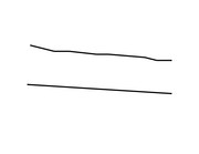
Here is a simple sketch showing the perturbated taper on top and straight on the bottom. The one on top only descends in girth throughout it’s length but looks quite different.