Blowing machine

Yes, that’s the form of Bernoulli’s equation we’re working with.

If we call the “mouth” of the blowing machine the inlet and the whistle window (or open air) the outlet, then we’re assuming p2 is zero, relative to atmospheric pressure. The earlier draft assumed v1 was negligible. The more recent draft doesn’t; the term -(A1/A0)^2 in Kb adjusts for a non-zero v1 = Q/A0. For a zero-length tube with no obstructions, and assuming A0 >> A1, we would have K = 1 and p1= rho/2v2v2.

However, it would seem that any obstruction, particularly the abrupt narrowing of the airflow between the mouth and the windway, would add an additional loss coefficient to K. Reading this, https://neutrium.net/fluid-flow/pressure-loss-from-pipe-entrances-and-exits/, I’m surprised that we don’t see a significant additional loss (which would show up in Ke) for whistles like the old Gen.

OK:

12 March 2023: Old Gen head after Flow Meters singly and in parallel, taped better.				
LH	RH	L+R	Press.	Res.
2		2	4	1.000
4		4	6	0.612
6		6	9	0.500
8		8	17	0.515
10		10	29	0.539
12		12	40	0.527
14		14	55	0.530
16		16	71	0.527
18		18	90	0.527
20		20	119.5	0.547
7	6.8	13.8	44	0.481
8	8	16	63	0.496
9	9.3	18.3	84	0.501
10	10	20	103	0.507
11	11.2	22.2	123	0.500
12	12.1	24.1	145	0.500
13	13	26	169.5	0.501
14	14	28	202	0.508
				
Average Resistance		0.55
Average Resistance above 4L/Min 0.51

So, yes we are seeing differences between single meter and paralleled meter readings. Can we identify why?

And note I’ve slipped a date into the data label. I’ll try to do that to help us keep track of changes to rig or thinking.

I set that up and had both meters reading 10. Pressure across lower meter already 614mm.
Increased flow to both reading 12. Pressure now 833mm
Started to close RH Needle Valve to pull it back to reading 10, but quickly exceeded the Manometer’s max, 1400!

So backed off back to 10 each with needle valve open, started closing it, while increasing flow and monitoring pressure to keep it below 1400.
Didn’t get very far: LH 9.7, RH 10, Pressure 1354.

So we’re reminded:

  • these meters have a lot of resistance (back pressure)
  • you don’t have to close the needle valve far to get a lot more!
  • the first meter in the chain reads lower when the pressure is on
  • the good news (I guess) is that we only saw a 3% droop in the LH meter at the enormous pressure of 1354mm. On our whistles we rarely get much above 300mm.

You’ll notice I didn’t use your first stop valve to control the flow. I did plumb it in and tried it. Being a ball valve, it’s very quick acting, and so unsuited to incremental control. I used the Pressure Regulator in conjunction with my recently added Resistor to control flow into the LH flow meter, etc. Hope that’s OK for your experiment. Clarify if I’ve misunderstood the instructions.

Any further instructions on this question?

Thanks, Terry. That answers my question, but I’m still in the dark about what’s going on.

When the RH meter was discharging to atmospheric pressure, and the LH meter was discharging into 13% higher pressure, the LH meter was reading only 3% lower. I would have expected the LH air density to be 13% higher, and that leads to only a 3% change in the reading? When you squeezed the tubing between the flowmeters, you got the upstream flowmeter to drop by 36%. Do you think that squeeze was enough to raise the pressure by an atmosphere or two?

When you put the two flowmeters in parallel in the experiment above, for say 100 mm pressure at the beak of the whistle, the pair of meters gave a flow reading about 7% higher than one meter on its own would have. Earlier, when you moved the flowmeter after the 30 x 4 calibrator instead of before, at 100 mm H20 across the calibrator, it was reading about 18% higher.

Anyone else have any ideas?

I’ll have a think about those questions, Tunborough.

But I’ve just been having a play on a bit of a whim. Remember earlier, I’d said:

“I’m imagining that we need to connect the end of the food chain to a servo-controlled vacuum source, connected to sense the pressure at the junction between whistle and flow meters, and strive to keep that at zero by cranking up the vacuum. That way both whistle and flowmeters will be functioning at atmospheric. This is the kind of stuff I used to have to design and build back in the Research School of Physical Sciences and the Research School of Earth Sciences at ANU. But fortunately fate intervened, and I became a fat-cat flute maker instead. Ahem…”

The notion of trying to balance out the pressure across the device-under-test by applying a vacuum where normally it vents to air has stayed with me. And I racked my brains, (both cells at once!) to remember what if any sources of vacuum I could pull into play. And then remembered a ghastly little airbed pump/sucker I had somewhere. I turned all the somewheres upside down and found the sucker. Mine is red, but it looks suspiciously like this one:

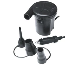
Connecting its Deflate port to the output side of a 20L/Min flow gauge revealed it was capable of sucking about 8 L/Min. I’d have liked more, and some way of controlling its suction, but beggars and choosers applies. Aha, “some way of controlling its suction”? You’ve got a variac, haven’t you? (Younger readers might need to look that word up. Essentially its an autotransformer - a crude electromagnetic way of controlling mains voltage via a big knob.) And sure enough, I can now control my vacuum flow from 0 to 8L/Min, and the vacuum pressure from 0 to -360mm.

So I set up the Pressure Regulator feeding the LH Flow Meter, feeding the 30 x 4mm calibrator, now feeding the suction pump, with a pressure takeoff between flow meter and calibrator. And wound up the Pressure Regulator for 20LMin flow with the sucker off. I could hear the flow coming out of the sucker blow hole and vents. The pressure meter showed 110mm - that’s the backpressure from the Calibrator and the so-far inactive suction pump. Now turn the pump on and start advancing the voltage from the variac, and the pressure meter drops down to zero. And if I keep going, starts indicating negative. The flow meter might have dropped a smidgeon - perhaps to 19.7 - rather hard to be sure of. But we are now operating with both the Calibrator and the Flow Meter at atmospheric pressure. A bit harder to do with a whistle but if we can run any calibrating tests with a Calibrator we would appear to be ahead.

So, of course, my mind races ahead. How far can we push this thing? I plumb in the 2nd flow meter, and crank up the flow. I can’t get all the way to 40Lpm and balance out the back pressure of the Calibrator and suction pump, but I can get to around 34.4. Pressure is now 306mm until balanced out by the added suction.

And so then comes the big question. The system is sitting there pushing 34 odd L/Min through the flow meters and calibrator, but we have the pressure at that junction balanced out by the suction. So I should be able to disconnect the lower end of the Calibrator from the sucker pump and it shouldn’t make any difference. We’re replacing “0mm pressure relative to atmospheric” with atmospheric itself. Sure enough, maybe a little flicker but not measurable.

So this suggests to me that we don’t have a significant problem with the simple setup of Pressure Regulator > Resistor > Flow meters including the valve> Manometer takeoff > Device-under-test > atmosphere. Sure there will be back pressure applied to the flow meters, but it doesn’t seem to affect them dramatically.

Have I convinced anyone? Does this new facility offer any new ways to further investigate your various concerns?

McGee, I swear, every day you make me laugh out loud !

Anyone who’s got a variac lying around is my kind of guy ! :slight_smile:

Nice touch ! I’ll do the same !

Once again, Terry, thank you for running the cases. Here’s the plot:

Some comments:

  1. At 5lpm, the two single-meter readings agree. Very glad to see that. The huge disparity with 2 meters went away.

  2. The blue + black cases track very closely. Actually, a 5% change in density puts blue right on top of black.
    (So, what could cause a 5% change in density ? From one day to the next ? One test-session to the next ?)

  3. There’s a down-bump at 10lpm (single meter) and 20lpm (2 meters), which is 10 on each. Honestly, that makes me wonder if there might be an error in the meters. Honestly, that’s my guess at this point.

  4. As to the difference between using 1 meter or 2 on the same day, I really am at a loss. There is a difference. It looks systematic, not random. I’ll think on it, but right now, I’m out of ideas.

At the risk of sounding foolish . . . wouldn’t it be nice to have a single flowmeter we could trust ?

Also, I confess, I haven’t had a chance to process all the traffic above. It’s just a lot all at once for me. It may take me a while.

Also, one little bit more.

Here are the screen-scaled increments Terry listed out a few days ago:

Never have I seen a sensor designed for lab use with a scale like that.

Well, you’ve got to admit I’ve picked an easy audience. The kind of people who will read 500 plus responses on a topic as dry as machine-blown flageolets are clearly desperate for entertainment!

Anyone who’s got a variac lying around is my kind of guy ! > :slight_smile:

Heh heh, it is over 55 years since I put it in a custom metal box I folded up myself. I made it to control a Scope soldering iron’s temperature in the days before we had temperature-controlled soldering. But perhaps surprisingly, I still use it all the time. It controls the speed of the hand-held Dremel tool I use for undercutting. And it controls the hot-wire polystyrene cutters I use to excavate the curved slots for flutes in my cases. And now it’s found a new job!

It would certainly be a lot easier to have a singe flowmeter that covered the range and had the resolution we need. In the same way that reading the Digital Manometer is so much easier than trying to judge which part of the meniscus to believe. But, consider this. We are now aware that if we perch the floating bead flow meter at a pressure higher than atmospheric, we introduce a source of error due to the denser air. The digital flow meter you were looking at is based (if I understand correctly) on cooling effect of air flow over a heated sensor. What happens to that cooling effect if we increase the pressure and the density of the air flowing through it? Do they talk about that in the specs?

I imagine that at least its resistance to air flow is probably pretty low. Again, do they talk about that in the specs?

I have been wondering if we should concentrate on measuring pressure rather than flow for our tests. I know Tunborough prefers flow, but if we could use calibrators to predict the relationship, the Manometer is non-intrusive and easy to use. But lets see where the journey takes us…

Thanks Tunborough for the confirmation and revised model.
This part

allows something I has been working towards saying but avoiding because of the complication of explaining where a number 4.1029 came from. If we rearrange that and set K=1 for a zero length windway and ignoring the inlet air speed as in the previous model we get

h*w= Resistance sqrt(rho)/0.2657 = Resistance4.1029

That’s the area of a hole in a thin sheet of metal or plastic that we can blow through to get a feel of what a whistle with a quoted Resistance feels like. The 4.1029 is a messy function of the density of air, the density of water, the number of seconds in a minute and various metric unit conversions all of which appear in Tunborough’s model.

We can take a PET soft drink bottle, drill an appropriate diameter hole in the cap, glue the cap back on and cut the bottle to make something like a funnel (I’ll explain all that later). A full forced inhale-forced exhale breath blown through it in 15 seconds is in the ball park of 12 L/min, depending on one’s lung capacity.

So when C&F has a sticky with measured McGee Resistances for various whistles we can get a feel for what they are like in terms of a hole in a bottle cap. We still won’t know how hard we have to blow for a particular note but we when we do we could work out roughly how long we could hold, say, a low G for.

The cone of bottle is a health and safety issue as the temptation to suck may be strong and breathing though a 3.94mm orifice in the windpipe until the medics remove the bottle cap might involve a sense of fear and breath control practice we could do without.

I haven’t absorbed the last tranche of posts yet but I think if the focus was on comparing existing whistles, or practical tinkering with the engineering, then measuring just pressure might serve. ‘stringbed’ has pointed out that it serves the recorder makers well. I’m hoping a zero length calibrator with remove enough potential contributions to K that we get an good idea which oddities are coming from the flow meters. Looking at all the fluid dynamics complications Tunborough is turning up what is going on in those flow meters, especially as the space above the ball gets smaller, is probably not simple. Or maybe their maker has trouble with its reamers.

With the anomalies we are seeing with the flowmeters in different configurations, I’m prepared to abandon them. We may not need the fudge factor that I’ve called Ke to get a good measure of air speed with the manometer alone. Before they go, though, I would appreciate trying a few more of the calibrators upstream of the flowmeter instead of downstream. 5, 10, 15, and 20 L/min should be enough to put Ke to rest.

So running the Manometer in Differential Mode. I still worry that the elevated pressure due to the high back pressure of the Flow Gauge will impact on the Calibrator results. (Convince me I’m wrong!) Indeed, have we ever measured that back pressure? I suspect not. Give me a few minutes…

Woah, interesting. So, Pressure Regulator via Whistle Connector (to take advantage of its Pressure Takeoff to the Manometer) through a Flow Gauge to air. I can only get to around 14-15L/Min when I run out of Manometer (1400mm H20). Tried both flow gauges, just in case.

What would you think of this setup and operating procedure for your Calibrator tests? Pressure Regulator via Flow Gauge to Whistle Connector (and Pressure Takeoff to the Manometer) through Calibrator-under-test to T-junction with Pressure Takeoff point to Vacuum pump. Manometer in Differential Mode, but at first connected only to upper takeoff point. Lower takeoff point tube folded over to block. Set up desired flow, wind up suction to bring upper pressure takeoff to zero. Then plug lower takeoff tube to Manometer other input. Take pressure reading.

Just did one to test. The 30 x 4mm Calibrator connected as above. With 20L going through it but suction off, the pressure at upper takeoff relative to air was 112mm. Balance that down to zero, connect up lower takeoff point and pressure across the calibrator is 60.

Ah but, pull off the vacuum pump and the pressure across the calibrator is still 60! And the flow still 20L. Doesn’t this tell us that the back pressure across the Calibrator is not enough to bother the Flow Meter? So our “Calibrator open to air” tests can be relied upon?

And that we can safely retire the Sucker? It’s demonstrated that it isn’t necessary?

Ah, but all very well, I hear you mutter. I asked for a reading of the Calibrator upstream from the Flow Gauge. Oh alright, I respond petulantly, but dutifully reconfigure in that mode. Ooooh, interesting. I’m now seeing about 50mm of pressure across the Calibrator at 20L. So, two possibilities (at least!):

  1. the relatively small resistance or back pressure of the Calibrator is messing with the Flow or the Flow Meter.
  2. the relatively high back pressure of the Flow Meter is messing with the Calibrator or perhaps the Manometer (though it didn’t complain).
  3. unknown, suggestions welcomed.

With 20L of flow still running through the Calibrator and Flow Meter, I pull out the calibrator and replace it with a coupler (about 8mm diam bore, 45mm long). Flow Gauge still reads 20L, pressure meter now reads 2mm. I reckon it’s Option No 2) above.

Heh heh, this is so much like any other significant science I’ve been involved in. 99% of the effort goes into developing the hardware and procedures. The actual experiment is over in minutes.

Yes, I’ve looked at 2 manufacturers, they describe how the MEMS sensors work. Forced convection.

Indirectly. The spec sheet claims a “pressure loss” of less than 1 kpa (that’s 1/100th of 1 atmosphere).

So, with such a low-pressure-loss sensor, the change in pressure and density will be very tiny. No need to worry about huge pressure+volume+density changes.

See above.

My understanding of the model-in-progress contributed by Tunborough is that each whistle has a “coefficient” (K, Cd, WR - cousins all). Honestly, that was my hunch at the start of this thread. However, thinking more, I came to believe a flow-dependance (descending Cd) would be reasonable. Big factor ? I don’t know. Depends on how the flow model will be used. But, we observed direct measurements supporting that once the “shifted” tape was fixed.

My perspective is: We are so close . . .

We’ve got: reliable pressure measurements, a well-exercised test+data-collection protocol, willing analysts (on 3 continents !), and a model-in-progress. With a good flow sensor, we could have a very clear picture.

I mean, taking a step back, the existing flowmeters are kind of a blurry lens, but they have allowed plenty of progress. And, frankly, it’s been fun trying to puzzle-out all the effects. Maybe they’re “good enough” for hobby-hackers.

But, really, wouldn’t it be nice ?

ps: the Amazon seller allows refunds for 30 days . . . my offer to cost-share still stands.


OK, so 102mm compared to something far exceeding 1400mm in the current Flow Gauges. And that presumably at 100L/Min, so we’d be seeing considerably less again. So that’s unlikely to bother anything upstream from it.

But I was thinking supposing you had a high resistance Calibrator or whistle at the end of the chain (ie after the Flow Gauge), is it likely that it’s back pressure would bother this kind of flow gauge. I can imagine that a sensor based on heat flow might be very sensitive to operating pressure and therefore air density. They don’t seem to give a “sensitivity to operating pressure” factor in the specs.

I was amused by the “Turn Down Factor” given as 80:1. My mind immediately interprets that as the number of girls you have to ask before you get a dance at the Prom. But it seems it means the gauge can be used down to Full Scale/80, about 1.25L/Min. That’s very acceptable. And it’s resolution looks very good too.


My understanding of the model-in-progress contributed by Tunborough is that each whistle has a “coefficient” (K, Cd, WR - cousins all). Honestly, that was my hunch at the start of this thread. However, thinking more, I came to believe a flow-dependance (descending Cd) would be reasonable. Big factor ? I don’t know. Depends on how the flow model will be used. But, we observed direct measurements supporting that once the “shifted” tape was fixed.

My perspective is: We are so close . . .

We’ve got: reliable pressure measurements, a well-exercised test+data-collection protocol, willing analysts (on 3 continents !), and a model-in-progress. With a good flow sensor, we could have a very clear picture.

I mean, taking a step back, the existing flowmeters are kind of a blurry lens, but they have allowed plenty of progress. And, frankly, it’s been fun trying to puzzle-out all the effects. Maybe they’re “good enough” for hobby-hackers.

But, really, wouldn’t it be nice ?

ps: the Amazon seller allows refunds for 30 days . . . my offer to cost-share still stands.

Let’s see what the others make of today’s tests. Are we near enough, or do we need sharper tools?

Why do we need a high-resistance calibrator ?

Why is a “high resistance” calibrator needed for operating condx far-removed from the pressure+flow of a whistle-player ?

I thought the calibrators were needed as a check on the flowmeters.

The spec sheets allows for operating pressures up to .6mPa (~6 atmospheres).

It’s true, the spec sheet states the accuracy given is for at 20C + 1atm. But a whistler blows barely above 1 atm.

My belief is that better knowledge of the flow will allow a better model.

Thoughts from the GMT timezone. I once worked briefly on a software project where the coders where in the UK and testers in Hong Kong. Never a break. A reminder that the whole world never sleeps.

Operating pressure clearly effects the flow meter reading in a way we don’t understand. The pressures that matter will be the ones either side of the float. So it’s the downstream-side pressure that matters most. My guess is that the backpressure is coming mainly from the adjuster on the inlet even when fully open. The scale spacings are interesting and tell us something non linear (even if only the bore taper) is going on. I would tend to accept that the makers know what they are doing - even if they are just calibrating what, on average, comes out of the mould.

If the flowmeter is downstream of the calibrator/whistle and open to atmosphere there should be a consistent (but not necessarily linear) relationship between actual flow and the scale reading for each test. Measuring the pressure across a calibrator is no problem - but unless the water manometer comes off the shelf we won’t know what the pressure is relative to atmosphere so we don’t know rho, the density of air. It’s also complicated to set up with a whistle (I am wondering if some container from the kitchenware section of the supermarket could be modified). There might be some latency if the container volume was large but that should be no problem for a blowing machine.

If the flowmeter is upstream of the calibrator/whistle the setup is simpler, especially for a whistle. We then have a flow reading that is a function of both actual flow and pressure. However, we are measuring the outlet side pressure on the flow meter and do know the density of air in the calibrator. It is also not much problem to leave the flow meter in the system and record it even if only planning to use the pressure - we might find we could use it if more information becomes available.

So I think have the flowmeter above the calibrator (and could probably use its adjuster to regulate flow and pressure). A full set of reading with the calibrators (including a zero length one) could then be enough to distinguish between flow measurement irregularities and flow dynamics changes in the calibrators. It would be possible to put a resistance downstream of the calibrator (with manomter in differential mode across the calibrator) to see how operating at an (unknown) higher pressure moved any features of interst on the graphs. Or to bring out the water manometer and know the pressure. It also saves Terry having to make and leak test constructions involving Tupperware boxes or whatever.

My main interest in the modelling is concern that we may be modelling noise or alternatively throwing out the baby with the bath water. I am also trying to get my head round the maths in a way that doesn’t obscure text book first principles and intuition**. For example the statement of Bernoulli’s equation I gave can cope with input velocity without involving K. It also highlights an approximation that we are making; we are assuminng flow of an incompressible fluid so rho is the same on both sides of the equation/calibrator. The shenanigins with the flow meters have reminded us that it is not.

**I suspect one of the reasons for mathematical rearrangements (complicated I suspect) that allow pressure losses to be accumulated into K is the earlier need to use a slide rule (younger readers may need to look that one up as well) and maybe ready-reckoner tables (ditto). Using a spreadsheet I tend to keep things separate.

And on the validity of the system at large. It would make sense to me to have a slightly higher resistance Calibrator than the hardest blowing whistle, a slightly lower resistance one than the easiest blowing whistle, and one in the mid range. And I’m still planning to do an orifice plate, just in case we learn something!

The spec sheets allows for operating pressures up to .6mPa (~6 atmospheres).

So it would definitely be safe in our system. But how accurate?

It’s true, the spec sheet states the accuracy given is for at 20C + 1atm. But a whistler blows barely above 1 atm.

The bit that bothers me is that the whistler covers a range of pressures, and if that were to be enough to introduce an error, it will be an error that varies with the pressure, not just a simple offset.

My belief is that better knowledge of the flow will allow a better model.

Agree, but we’d have to somehow convince ourselves that it can be trusted at the slightly higher pressures than a whistle or calibrator might reflect back.

You’d think that all flow meters would be capable of transcending pressure-related errors wouldn’t you. How do you make air flow without pressure?