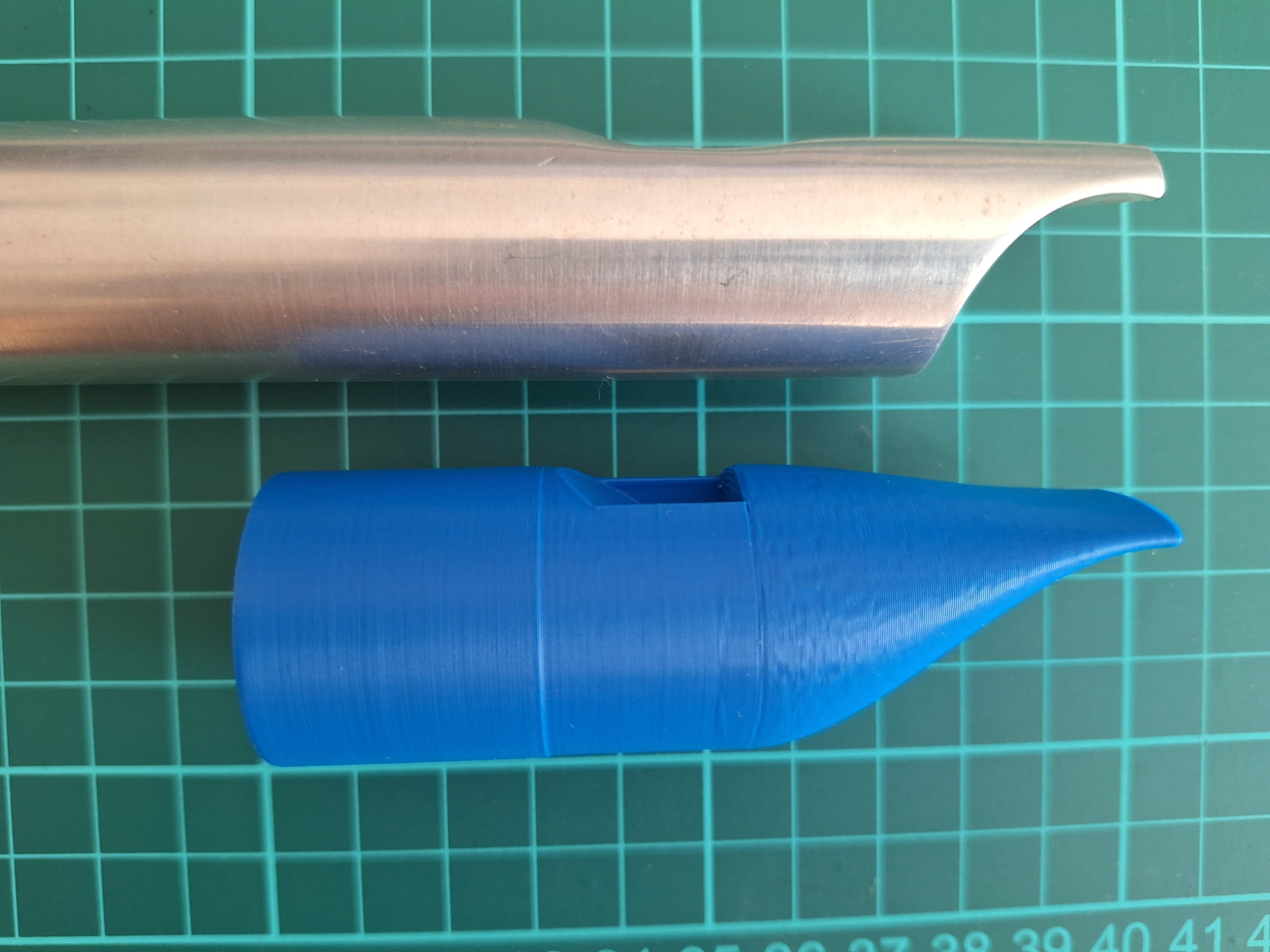
A Quick question: I have a low D design that works really well for me, the windway hight is 1.5mm, which I personally like but some players prefer more back pressure. If I make the windway hight 1.1mm will the windway offset automatically realign so it is level with the bottom of the hole? let me know if I need to post a picture to explain.
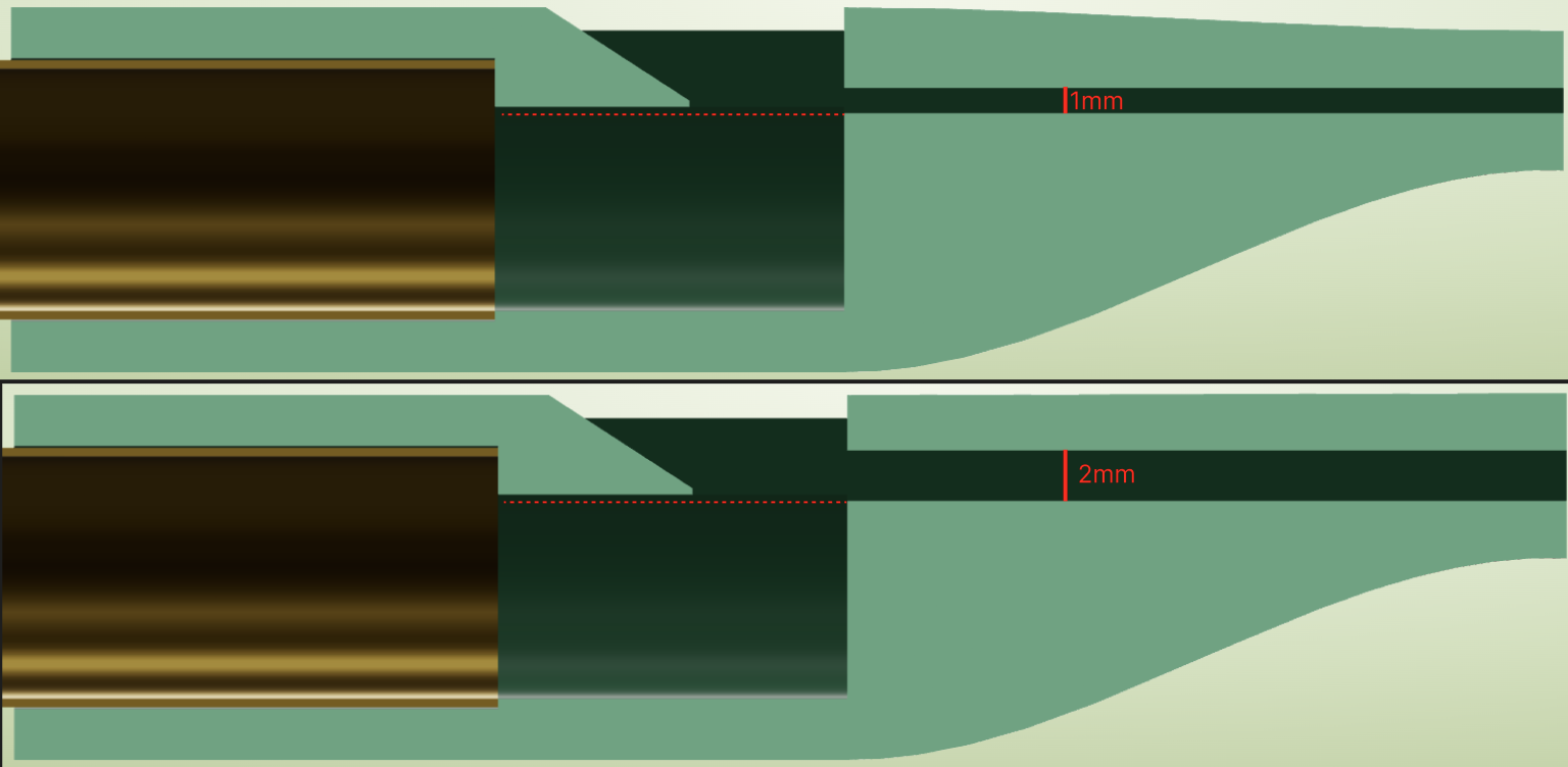
The windway height parameter moves the windway ceiling, leaving the floor in place. So I think the answer to your question is yes. Here’s an exaggerated cutaway for example (the dotted line doesn’t move in relation to the floor or labium):
When you talk about a concave mouthpiece, are you referring to the shape of the “beak”? The 3D printed mouthpiece has a much shallower ramp for its beak than your aluminum one. Would a parameter to control the “beak” radius be what you’re after?
paddler: “by constraining the space in which these swirls of air move, you change the timing of the repeating pressure build up at the labium, which will affect the frequency.”
With apologies to the OP for latching on to the slight diversion. Is it affecting the frequency of the jet (so after constraining the space a change in breath pressure might bring it back to match the air column) or is it changing the resonance of the air column (the way that, if I understand it right, the presence of the jet influences the end effect at the window) ?
I’d say it is probably the latter, but I expect there are a whole bunch of factors that interact in a complex way, so take my explanation below as the oversimplification that it is.
My expectation is that constricting the air flow at the open end of a resonating pipe like that causes the air flow to accelerate. This increases its inertia and hence inhibits the reversals of flow direction that occur with every vibration of the air column, which lowers the resonant frequency.
And in practice, if you narrow the foot end, or shade/constrict the window or embouchure end of flutes, you do experience a flattening effect.
You can generalize this to other parts of the bore where air movement is maximum and pressure is constant (these are the pressure nodes for its various resonant frequencies). Constrictions at those locations also have the effect of lowering the resonant frequency, for the same reason.
@paddler Thanks. Am still getting my head round what is driving what - and realising that it is all one thing.
@smish Fascinating simulation thanks. Am I reading the simulation display correctly (and on my desktop I have plenty of time to read it) that the jet is flipping either side of the labium much more slowly that the frequency of the standing wave? The ‘probe in the bore’ pressures and the faint pressure wave in the bore match the frequency of the bore length I entered but on that run the jet hasn’t flipped yet.
It looks to me like the jet’s period of oscillation (flipping back and forth) matches that of the pressure probe in the bore, once the system has reached a dynamic steady state.
However, it should be noted that the equations in that simulation are a 2D simplification, not a cross section of a real 3D whistle geometry, so its numerical results are not expected to rigorously match real-life whistles. In this case though, I expect the wedge producing an instability which leads to oscillation to be qualitatively correct.
I’m interested in doing the more accurate 3D simulations too, but they’re too expensive to solve interactively in a browser.
Ah yes, it occurred to me later that I should have left it running overnight. I guess those first waves in the tube could be a response to the initial disturbance.
Edit to add: Having let it stabilize I see that the jet was flipping but most of the flow was outwards - not quite like your animation above. Easier to see having reduced the jet speed to get the first mode.